Electric Substation Guide: Power Distribution, Protection Systems, and Maintenance
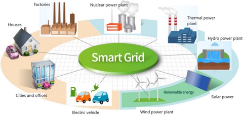
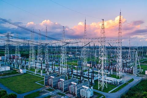
An electric substation is a critical part of the power grid that helps transform, control, protect, and distribute electricity. Substations connect generation facilities, transmission networks, distribution systems, and large electricity customers.
Depending on their function, substations may increase or decrease voltage, route electricity between circuits, isolate faults, regulate voltage, monitor electrical conditions, and provide protection for expensive equipment.
Modern substations increasingly combine traditional electrical equipment with digital monitoring, automated controls, communications systems, and advanced protection technology.
Substation planning is particularly important as electricity demand grows because of data centers, industrial electrification, electric vehicles, renewable generation, battery storage, and new commercial development.
What Is an Electric Substation?
An electric substation is a facility containing electrical equipment used to transform voltage, switch circuits, regulate electrical conditions, and protect the power system.
OSHA describes substations as locations within electric transmission and distribution systems that can serve as transmission switching points, voltage-transformation and regulation points, and sources for distribution circuits.
A typical substation may include:
Power transformers
Circuit breakers
Disconnect switches
Busbars
Current transformers
Potential or voltage transformers
Protective relays
Surge arresters
Grounding systems
Control panels
Battery systems
Communication equipment
Metering equipment
SCADA equipment
Fencing and security systems
Substations can be located outdoors, indoors, within industrial facilities, or at specialized grid facilities.
Main Types of Electric Substations
Transmission Substations
Transmission substations operate at high voltage and connect major transmission lines with other transmission circuits or lower-voltage networks.
They may perform:
Voltage transformation
Circuit switching
Fault isolation
Power-flow management
System protection
Transmission interconnection
Large transmission substations can contain multiple transformers, high-voltage breakers, extensive bus arrangements, and sophisticated protection systems.
Distribution Substations
Distribution substations reduce transmission or subtransmission voltage to levels suitable for local distribution networks.
They commonly supply:
Commercial buildings
Residential areas
Industrial facilities
Schools
Hospitals
Municipal infrastructure
Distribution substations may also include voltage regulation and feeder protection equipment.
Switching Substations
A switching substation primarily routes electricity between circuits without necessarily performing major voltage transformation.
Circuit breakers and disconnect switches allow operators to change network configurations and isolate selected sections during faults or maintenance.
Collector Substations
Collector substations are commonly associated with renewable-energy projects.
For example, a utility-scale solar or wind facility may collect electricity from multiple generating units before transferring it into a higher-voltage transmission network.
Customer Substations
Large industrial facilities and other high-load customers may have dedicated substations that transform incoming utility power for internal distribution.
These installations can support manufacturing plants, data centers, mining operations, transportation infrastructure, and large commercial facilities.
How an Electric Substation Works
The exact sequence depends on the substation design, but a simplified power path may look like:
Transmission line → circuit breaker → busbar → transformer → distribution feeder → customer
Electricity enters the substation through incoming transmission or distribution circuits. Switching and protection equipment controls the flow before a transformer changes the voltage when required.
The lower-voltage output may then pass through additional switching and protection equipment before entering distribution feeders.
Protection systems continuously monitor electrical conditions. If a serious fault is detected, a protective relay can command the appropriate circuit breaker to open and isolate the affected equipment or circuit.
Power Transformers
The power transformer is one of the most important components in many substations.
Transformers transfer electrical energy between circuits at different voltage levels through electromagnetic induction.
Important transformer components can include:
Transformer tank
Windings
Core
Bushings
Insulating fluid
Radiators
Cooling fans
Tap changer
Conservator system
Pressure-relief equipment
Temperature monitoring
Oil-level indicators
Transformer selection depends on:
Voltage levels
Capacity
Load profile
Cooling requirements
System configuration
Environmental conditions
Short-circuit requirements
Future expansion
Transformer condition monitoring is important because transformer failures can cause significant outages and require lengthy replacement or repair processes.
Substation Switchgear
Switchgear allows electrical circuits to be controlled, protected, and isolated.
Common equipment includes:
Circuit breakers
Disconnect switches
Grounding switches
Fuses
Busbars
Metal-enclosed switchgear
Gas-insulated switchgear
Air-insulated switchgear
Circuit breakers can interrupt fault current when commanded by the protection system.
Disconnect switches are generally used to provide visible or defined isolation and are not normally intended to interrupt high fault current unless specifically designed for that purpose.
The correct equipment depends on voltage level, fault current, environmental conditions, space limitations, and system configuration.
Substation Protection Systems
Protection systems are designed to identify abnormal electrical conditions and isolate affected sections quickly.
A typical protection scheme may include:
Protective relays
Current transformers
Voltage transformers
Circuit breakers
Communication channels
Trip circuits
Battery-backed control power
Backup protection
Protection functions may include:
Overcurrent protection
Differential protection
Distance protection
Ground-fault protection
Overvoltage protection
Undervoltage protection
Frequency protection
Transformer protection
Bus protection
Breaker-failure protection
Protection settings must be coordinated so that the appropriate device operates while minimizing unnecessary disruption to healthy portions of the grid.
Current and Voltage Transformers
Instrument transformers provide scaled electrical signals to protection, control, and metering equipment.
Current transformers (CTs) reduce large primary currents to measurable secondary values.
Voltage transformers (VTs) or potential transformers provide scaled voltage signals.
These devices allow relays and monitoring equipment to analyze system conditions without directly connecting sensitive control equipment to the full system voltage or current.
Incorrect CT or VT configuration can affect protection accuracy, so installation, testing, polarity, ratio, and wiring require careful verification.
Substation Busbars
A busbar is a conductive connection point that allows multiple circuits to connect within a substation.
Common bus arrangements include:
Single bus
Double bus
Main-and-transfer bus
Ring bus
Breaker-and-a-half configuration
The appropriate arrangement depends on reliability requirements, switching flexibility, fault isolation, space, expansion plans, and project economics.
More complex bus configurations can provide additional operational flexibility but also increase equipment and protection complexity.
Substation Grounding
Grounding is fundamental to substation safety and protection.
A grounding system may include:
Ground grid
Ground conductors
Ground rods
Equipment bonding
Fence grounding
Transformer grounding
Surge-protection grounding
A properly designed grounding system helps manage fault currents and hazardous voltage differences.
OSHA specifically requires conductive substation fences to be grounded and addresses guarding, access, and working-space requirements around substation equipment.
Grounding design commonly considers soil resistivity, fault current, grid geometry, touch voltage, step voltage, and clearing time.
Substation Control Systems and Automation
Modern substations increasingly use digital controls and automation.
Technologies may include:
SCADA
Remote terminal units
Intelligent electronic devices
Digital protective relays
Automated switching
Remote monitoring
Condition monitoring
Communications networks
Substation automation systems
These technologies can provide operators with information about:
Voltage
Current
Breaker status
Transformer temperature
Protection alarms
Fault conditions
Equipment condition
Power flow
Automation can improve operational visibility, but it also increases the importance of communications reliability and cybersecurity.
Substation Batteries and DC Systems
Substations often use battery-backed DC systems to operate protection and control equipment when AC station power is unavailable.
A substation battery system may support:
Protective relays
Circuit-breaker trip coils
Closing circuits
Control systems
Emergency lighting
Communications equipment
Alarm systems
Battery systems require appropriate monitoring, inspection, charging systems, ventilation where applicable, and periodic testing.
Substation Maintenance
A preventive maintenance program should be based on equipment manufacturer instructions, system criticality, operating history, inspection results, and applicable standards.
Maintenance activities may include:
Visual inspections
Transformer inspection
Oil testing where applicable
Breaker testing
Relay testing
Battery testing
Grounding-system inspection
Thermographic inspection
Insulator inspection
Surge-arrester inspection
Switch inspection
Cable inspection
Control-system testing
Protection-system verification
Vegetation management
Fence and access inspection
Maintenance schedules vary significantly by equipment type and operating environment.
Transformer Maintenance
Transformer maintenance may include monitoring:
Oil condition
Moisture
Dissolved gases
Temperature
Oil level
Bushing condition
Cooling-system operation
Tap-changer condition
Leakage
Pressure
Vibration
Oil analysis can provide information about certain developing transformer problems. Dissolved-gas analysis may help identify abnormal thermal or electrical activity, but test results should be interpreted by qualified specialists.
Circuit Breaker Maintenance
Circuit breakers may require:
Contact inspection
Timing tests
Insulation testing
Mechanism inspection
Lubrication where specified
Operating-cycle testing
Trip and close-coil testing
Control-circuit verification
Gas or vacuum-condition checks, depending on breaker technology
Maintenance requirements vary by breaker design, voltage class, operating frequency, environment, and manufacturer recommendations.
Protection Relay Testing
Protection relays should be tested to verify that their settings and functions operate as intended.
Testing may examine:
Pickup values
Trip timing
Logic
Communication
Input signals
Output contacts
Breaker trip circuits
Protection coordination
Backup protection
Changes to protection settings should follow documented engineering and change-control procedures.
Common Substation Problems
Transformer Overheating
Possible causes include:
Excessive loading
Cooling-fan failure
Blocked radiators
High ambient temperature
Low oil level
Internal problems
Temperature alarms should be investigated according to the equipment manufacturer's procedures.
Circuit Breaker Failure
Potential causes include:
Mechanical problems
Control-power failure
Worn contacts
Trip-coil problems
Incorrect protection signals
Communication failures
Breaker-failure protection can provide additional protection when a breaker does not interrupt a fault as expected.
Relay Misoperation
Possible causes include:
Incorrect settings
CT saturation
Wiring problems
Communication failures
Software configuration errors
Testing or commissioning issues
Protection-system changes should be reviewed carefully because incorrect settings can cause unnecessary outages or inadequate fault clearing.
Insulation Problems
Insulation deterioration can result from:
Moisture
Contamination
Aging
Electrical stress
Thermal stress
Mechanical damage
Inspections and appropriate electrical tests can help identify deterioration before failure.
Substation Safety Planning
Substation work can involve high-voltage electrical hazards, arc-flash risks, induced voltage, stored energy, fall hazards, and other workplace risks.
OSHA's electric power generation, transmission, and distribution requirements address safe work practices for these environments. The rules include requirements concerning hazardous-energy control, energized work, grounding, protective equipment, training, and substation-specific precautions.
Safety planning should include:
Qualified-person requirements
Access control
Lockout/tagout
Job briefings
Electrical hazard assessment
Grounding procedures
Minimum approach distances
Arc-flash assessment
Appropriate PPE
Insulating equipment
Emergency response
Communication procedures
Switching procedures
Equipment identification
Barricades and warning signs
OSHA's substation requirements include sufficient access and working space, grounding of conductive fences, controls for draw-out circuit breakers, and guarding of exposed energized parts.
Substation Inspection Checklist
A practical inspection program may review:
Transformer condition
Oil or insulating-fluid condition
Cooling equipment
Circuit breakers
Disconnect switches
Protective relays
CTs and VTs
Surge arresters
Busbars
Insulators
Grounding system
Battery system
Control panels
Communication equipment
Security fencing
Drainage
Vegetation
Lighting
Fire protection
Warning signs
Access controls
Inspection findings should be documented and prioritized according to safety, reliability, equipment condition, and operational importance.
Grid Modernization and Digital Substations
Substations are increasingly becoming part of broader grid-modernization programs.
Digital technologies can support:
Remote condition monitoring
Automated fault detection
Digital protection
Predictive maintenance
Asset-health scoring
Remote switching
Advanced power-quality monitoring
Integration with renewable generation
Battery storage coordination
Improved outage management
Digital substations may reduce the amount of manual information collection required, but they also introduce additional communications and cybersecurity considerations.
U.S. Standards and Regulatory Considerations
Substation projects may involve federal, state, local, utility, and industry requirements.
Important references can include:
OSHA 29 CFR 1910.269: Electric power generation, transmission, and distribution work requirements.
OSHA 29 CFR 1926 Subpart V: Construction requirements for electric power transmission and distribution.
National Electrical Safety Code (ANSI/IEEE C2): Electrical safety and utility infrastructure guidance.
NFPA 70: National Electrical Code provisions applicable to relevant electrical installations.
NFPA 70E: Electrical safety-related work practices for many workplace electrical environments.
IEEE standards: Guidance covering grounding, protection, transformers, switchgear, and other substation technologies.
NERC reliability standards: Applicable to portions of the bulk electric system.
Local utility requirements: Interconnection, protection, metering, construction, and operating requirements.
Local building and fire authorities: Requirements applicable to substation facilities and equipment.
Requirements depend on voltage level, ownership, facility type, jurisdiction, and whether the installation forms part of the bulk electric system.
Recent Developments in Substation Technology
Current industry developments include:
Digital protective relays
Online transformer monitoring
Automated substations
Advanced condition monitoring
Grid-edge sensors
Remote switching
Digital twins
Predictive maintenance
Advanced cybersecurity
Renewable-energy interconnection
Battery-storage integration
Grid-enhancing technologies
Growing electricity demand is also increasing attention on transformer capacity, substation expansion, and transmission and distribution planning.
Tools and Resources
Useful resources for substation planning and maintenance include:
Electrical single-line diagrams
Protection coordination studies
Short-circuit studies
Load-flow studies
Arc-flash studies
Grounding studies
Transformer test records
Circuit-breaker test records
Relay test reports
Thermographic inspection records
Battery test records
Asset-management software
SCADA systems
Condition-monitoring platforms
OSHA electrical safety resources
NERC reliability materials
IEEE technical standards
Utility engineering specifications
Frequently Asked Questions
What is the main purpose of an electric substation?
An electric substation transforms voltage, switches electrical circuits, regulates power-system conditions, and protects equipment and networks.
What equipment is found in a substation?
Common equipment includes transformers, circuit breakers, disconnect switches, busbars, protective relays, instrument transformers, surge arresters, grounding systems, control equipment, batteries, and communications systems.
Why are protection relays important?
Protection relays monitor electrical conditions and can initiate circuit-breaker operation when abnormal conditions or faults are detected. Proper coordination helps isolate affected sections while limiting disruption elsewhere.
How often should a substation be maintained?
There is no universal interval for every substation. Maintenance frequency depends on equipment type, voltage level, manufacturer guidance, operating environment, system criticality, inspection findings, and applicable requirements.
What are the major safety risks in substations?
Major hazards can include electric shock, arc flash, high-voltage exposure, induced voltage, stored energy, falls, and unexpected equipment operation. Only appropriately qualified and authorized personnel should perform applicable substation work.
Conclusion
Electric substations connect major parts of the power system and perform essential functions involving voltage transformation, switching, protection, control, and distribution.
Reliable substation operation depends on correctly selected transformers and switchgear, coordinated protection systems, effective grounding, accurate monitoring, planned maintenance, and strong electrical safety practices.
As electricity demand grows and renewable generation, battery storage, and digital technologies expand, substations are becoming increasingly important to grid modernization. Utilities and facility operators should combine asset management, condition monitoring, protection engineering, cybersecurity, and safety planning when managing substation infrastructure.

Related Post...
Commercial Solar Battery Guide: Energy Storage, Backup Power, and Facility Planning
Updated: September 15, 2026
Read More
1031 Exchange Guide: Investment Property Transfers, Tax Rules, and Planning
Updated: September 14, 2026
Read More
Commercial Building Inspection Guide: Structural Reviews, Systems, and Property Planning
Updated: September 15, 2026
Read More